Spot welding defects can quietly compromise product strength, consistency, and production efficiency – often before they’re even noticed. If you’ve dealt with weak welds, burn-through, or costly rework, you already know how frustrating and expensive these issues can be. This guide breaks down the most critical problems and how to fix them, helping you better control weld quality and prevent common spot-welding problems before they impact your process.
Why Do Spot Welding Defects Happen?
At its core, spot welding depends on a precise balance of heat (current), pressure (electrode force), and time. When any of these variables drift outside optimal ranges, defects begin to form (sometimes visibly, sometimes internally). In real production environments, this balance is often disrupted by:
- Incorrect welding parameters (current too high/low, wrong timing)
- Material inconsistencies (coatings, thickness variation, contamination)
- Electrode wear or misalignment
- Machine instability or poor maintenance
Even small deviations, such as slight electrode wear or surface oil, can significantly affect weld quality. That’s why understanding both causes and corrective actions is essential, not optional.
What Are Common Spot Welding Defects?
Below are the 8 defects you’re most likely to encounter, along with clear causes and actionable fixes.
Expulsion (Spatter)
Expulsion occurs when molten metal is forcefully ejected from the weld zone, often seen as sparks or splatter. It weakens the weld and creates inconsistent nuggets.
Causes
- Welding current too high: generates heat faster than the electrode force can contain
- Electrode force too low: insufficient clamping allows molten metal to escape before the nugget can consolidate
- Surface contamination: oil, scale, or zinc coating creates localized resistance spikes
- Worn or misaligned electrodes: uneven contact pressure creates hot spots
- Weld time too long: sustained heat input exceeds the containment capacity of the weld zone
How To Fix
- Reduce welding current by 5–10% increments and run test welds after each adjustment
- Increase electrode force to improve containment of the molten zone
- Clean sheet surfaces before welding: degrease thoroughly, remove mill scale where possible
- Inspect electrode tip geometry; dress or replace tips showing wear or edge rounding
- Verify electrode alignment: off-center contact is a frequently overlooked cause of asymmetric expulsion
Note: Slight expulsion may be acceptable in some applications, but consistent expulsion indicates unstable parameters.
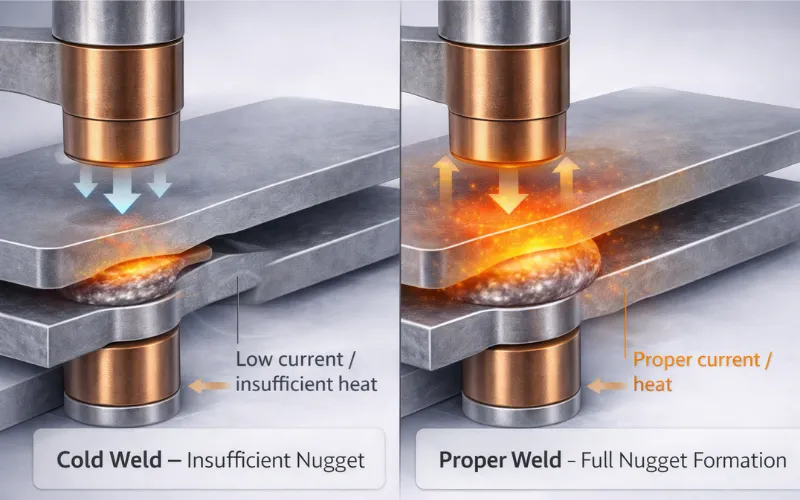
Insufficient Weld Nugget (Cold Weld)
A cold weld results in a small or weak nugget that lacks proper fusion, leading to low joint strength.
Causes
- Welding current too low: insufficient heat generation at the faying interface
- Weld time too short: current terminates before a full nugget develops
- Electrode force too high: excessive cooling from electrode contact suppresses heat buildup
- Electrode tip diameter too large: spreads current density too low to reach fusion temperature
- Shunting (a commonly overlooked cause): current takes an easier path through an adjacent previous weld instead of through the intended weld zone, leaving the new weld severely underheated
How To Fix
- Increase welding current incrementally, but verify against your established weld lobe to avoid crossing into expulsion territory
- Increase weld time modestly (often more controllable than large current changes)
- Check the electrode tip diameter against the specification for your sheet thickness
- Maintain minimum weld pitch spacing — AWS D8.1M provides minimum center-to-center distances specifically to prevent shunting
- Implement periodic peel testing as a production checkpoint
Pro tip: Always validate nugget size using peel or destructive testing when adjusting parameters.
Cracking
Cracks may appear on the surface or inside the weld, often compromising structural integrity.
Causes
- Excessive heat input (current or time too high): creates an oversized nugget with greater thermal contraction upon cooling.
- Rapid cooling: short hold time or no post-heat pulse forces the nugget to solidify under high thermal gradients and tensile stress.
- High-carbon or high-alloy steels: materials with poor weldability (high carbon equivalent) are inherently prone to solidification cracking.
- Contamination in the base metal: sulfur and phosphorus segregate to grain boundaries and weaken them during solidification.
- High restraint from rigid fixturing: prevents the joint from accommodating natural thermal contraction.
- Inadequate forge/hold force during the cooling phase allows the nugget to pull itself apart as it shrinks.
How to Fix
- Apply a post-weld temper pulse: reheats the nugget just enough to slow the cooling rate and relieve residual stress. It dramatically reduces cracking in press-hardened and dual-phase steels.
- Verify material chemistry: check the carbon equivalent (CE) and adjust the weld schedule accordingly. Materials with CE > 0.40 almost always need temper pulse schedules.
- Extend hold time (forge delay) to maintain electrode clamping pressure during solidification, constraining the nugget against shrinkage cracking.
- Reduce welding current to limit nugget size to the specification range; a smaller nugget experiences less total contraction.
- Use pulsed or stepped current profiles for crack-prone materials rather than a single continuous weld pulse.
Porosity and Internal Voids
Porosity refers to trapped gas pockets inside the weld nugget, reducing strength and reliability.
Causes
- Surface contamination: oil, grease, paint, or drawing compounds on electrode-contact or faying surfaces vaporize and become trapped.
- Moisture: water on sheet surfaces or absorbed in coatings generates steam that cannot escape during rapid solidification.
- Zinc coating vaporization: the primary cause in galvanized steel applications.
- Excessive heat input: drives vaporization of surface materials before the nugget periphery seals.
- Insufficient electrode force: fails to apply adequate forging pressure to close shrinkage voids during solidification.
How to Fix
- Clean both the electrode-contact and faying (interior) surfaces thoroughly before assembly and welding.
- For galvanized materials, implement a pulsed welding schedule with a defined pre-heat pulse to allow zinc vapor outgassing before the main current pulse.
- Increase electrode force to apply forging pressure during the solidification phase, which physically closes shrinkage voids before they can stabilize
- Verify that the hold time is sufficient for the nugget to fully solidify under electrode pressure before force is released.
- If porosity persists on coated materials after parameter adjustment, review coating weight specification (heavier zinc coatings require more aggressive schedule modifications).
Note: Porosity is often invisible; use non-destructive testing if quality is critical.
Excessive Electrode Indentation
Deep marks or dents on the material surface are caused by excessive pressure or heat.
Causes
- Welding current too high: excessive heat softens the sheet material directly beneath the electrode face, allowing it to deform under electrode pressure
- Weld time too long: prolonged current flow extends the overheating period, deepening the softened zone
- Electrode face diameter too small: concentrates electrode force over a reduced contact area, increasing contact pressure and localized deformation
- Mushroomed or worn electrode face: changes the contact geometry unpredictably, often increasing effective pressure at the contact perimeter
- Electrode force too high relative to heat input: mechanically drives the softened sheet material downward
How to Fix
- Reduce welding current and/or weld time to limit heat buildup in the electrode-contact zone
- Verify electrode face diameter matches the specification for your material thickness
- Implement a consistent electrode dressing schedule based on weld count rather than visual inspection alone; maintain correct face geometry proactively
- Measure indentation depth with a depth gauge if visual assessment is ambiguous; do not rely on visual estimation for specification compliance decisions
- Review electrode force settings if indentation persists after current reduction – high force combined with moderate current can still produce excessive indentation in thin materials
Note: Some indentation is normal, but excessive marks indicate energy imbalance.
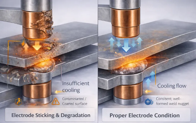
Electrode Sticking and Degradation
Electrodes stick to the workpiece or wear out quickly, affecting consistency and increasing downtime.
Causes
- Welding galvanized or coated steels: zinc alloys aggressively with copper electrodes, accelerating pickup, pitting, and mushrooming
- Excessive current at the electrode-sheet interface: promotes diffusion bonding between the electrode face and the workpiece surface
- Insufficient cooling water flow: allows electrode tip temperature to climb, accelerating alloying and softening of the copper
- Insufficient electrode force: increases contact resistance at the electrode-sheet interface, generating excess heat at the surface rather than at the faying interface
- Contaminated electrode face: debris buildup creates hot spots that accelerate local degradation
How to Fix
- Establish tip-dress intervals by material type: every 200–500 welds for galvanized steel, every 500–1,000 for bare mild steel. Do not rely on calendar-based schedules or operator judgment
- Use RWMA Class 2 (Cu-Cr-Zr) electrodes for steel applications: they offer the best balance of conductivity, hardness, and wear resistance
- Define electrode replacement criteria: maximum tip face diameter (measured with calipers or go/no-go gauge) and minimum shank length
- Verified cooling water flow exceeds 4 L/min at temperatures below 25°C. Inadequate cooling is one of the most common and easily correctable causes of accelerated electrode wear
- Implement stepper programs on automated lines that incrementally increase current as the electrode wears, maintaining a consistent nugget size across the entire electrode life
Note: Electrode condition directly affects weld quality. You have to monitor it regularly, not reactively
Wrong Welding Parameters
General instability in weld quality due to incorrect combinations of current, time, and pressure.
Causes
- Incorrect balance between current, time, and pressure
- Using the same parameters for different materials or thicknesses
- Lack of standardized welding procedures
- Machine calibration drift over time
- Operator-dependent setup variations
How to Fix
- Develop a qualified weld schedule for each material and thickness combination instead of relying on generic settings
- Use a parameter window approach (min–max range) rather than fixed values to handle real production variation
- Regularly calibrate welding machines to ensure consistent current output and timing accuracy
- Implement real-time monitoring systems to track current, resistance, and electrode displacement
- Train operators to follow standardized setup procedures and avoid manual guesswork
Remember this: Many defects are not caused by a single wrong parameter but by a poor combination of all three variables (current–time–force). Treat them as a system, not individually.
Burn-Through (Perforation)
Burn-through occurs when excessive heat melts completely through the material, creating holes.
Causes
- Excessive welding current
- Overly long weld time
- Insufficient electrode force to contain molten metal
- Thin or highly conductive materials
- Poor heat dissipation due to inadequate cooling
How to Fix
- Reduce current and weld time to control total heat input
- Increase electrode force to better contain the molten weld pool
- Use larger electrode tips to distribute heat over a wider area
- Adjust parameters based on material thickness and conductivity rather than using default settings
- Improve cooling efficiency (electrode water flow, cycle timing) to prevent heat buildup
Note: Burn-through is often a sign that the process is operating outside the safe thermal window. Instead of only lowering current, consider adjusting all three factors (current, time, and force) to regain balance without compromising weld strength.
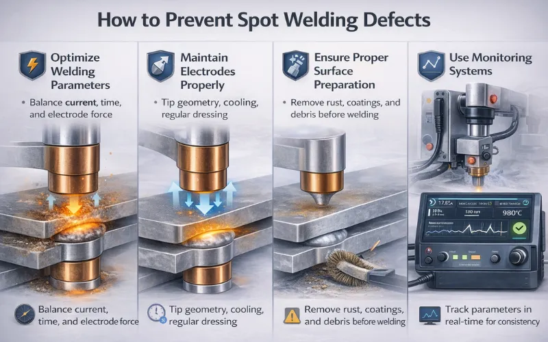
How to Prevent Spot Welding Defects?
Preventing spot welding defects is not just about fixing issues after they occur – it’s about building a stable, repeatable process that consistently delivers high-quality welds. Modern manufacturing increasingly relies on data-driven control, predictive maintenance, and tighter process standardization to minimize variability and defects. Below are the most effective and up-to-date practices:
Optimize Welding Parameters
Achieving the right balance between welding current, time, and electrode force is fundamental to defect prevention. Even small deviations can lead to expulsion, weak nuggets, or burn-through.
- Establish a weld schedule window (not just a single setting) to account for material variation and thickness tolerances
- Use adaptive welding controllers that automatically adjust current based on real-time feedback
- Validate parameters through destructive testing (peel tests, nugget size checks) during setup and periodically in production
- Monitor key variables such as dynamic resistance and heat input to detect instability early
Maintain Electrodes Properly
Electrodes play a critical role in heat generation and current flow. Poor electrode condition is one of the most common hidden causes of defects.
- Implement a regular dressing schedule to maintain electrode tip geometry and contact area
- Use high-quality electrode materials (e.g., CuCrZr alloys) suited for your application
- Ensure proper cooling water flow and temperature control to prevent overheating and degradation
- Track electrode wear using cycle counters or predictive maintenance systems
Ensure Proper Surface Preparation
Contaminated or inconsistent surfaces can significantly affect weld quality by increasing resistance unpredictably.
- Remove oil, rust, coatings, and oxides before welding using mechanical or chemical cleaning methods
- Standardize incoming material conditions to reduce variability between batches
- Pay special attention to coated steels (e.g., galvanized), where improper preparation can lead to expulsion or porosity
- Store materials in controlled environments to avoid moisture or contamination buildup
Use Monitoring Systems
Modern spot welding increasingly depends on real-time monitoring and data analytics to ensure consistency and detect defects before they escalate.
- Install in-process monitoring systems that track parameters like current, voltage, displacement, and resistance
- Use AI-powered quality monitoring to identify abnormal weld signatures and predict defects
- Integrate welding data into MES or quality management systems for traceability and continuous improvement
- Set up alarm thresholds and automatic rejection systems to prevent defective parts from moving downstream
Conclusion
Spot welding defects are not random; they result from controllable variables. By understanding the relationship between heat, pressure, time, and material behavior, you can quickly diagnose issues and apply the right fixes. More importantly, by maintaining proper parameters, equipment, and material preparation, most defects can be prevented before they occur, which saves both time and cost in production.
FAQs
Expulsion and weak welds (cold welds) are among the most common defects, typically caused by improper current and pressure settings.
Weak welds usually result from insufficient heat input, short weld time, or poor surface contact between materials.
Yes. Non-destructive testing methods such as ultrasonic inspection and thermal imaging can identify internal defects without destroying the weld.