Struggling to get consistent, high-quality joints in sheet metal work? Spot welding often looks simple, but small parameter mistakes can lead to weak welds, defects, or costly rework. This guide bridges that gap with clear, practical insights to help you understand the process, avoid common pitfalls, and improve results. Whether you’re new or refining your skills, you’ll gain a structured, expert-backed view of resistance welding and what truly drives performance.
What is Spot Welding?
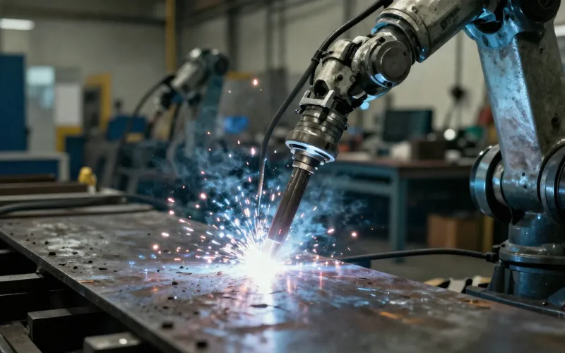
Spot welding is a resistance welding process used in metal joining to connect two or more sheet metal parts by applying mechanical pressure and passing a high-density electric current through a small contact area using conductive electrodes. The heat generated from electrical resistance produces localized melting in the fusion zone, forming a solid joint called a weld nugget; after the current stops, a short cooling phase allows the material to solidify, resulting in strong mechanical strength. This method is widely applied in manufacturing processes such as automotive production and automated welding systems, where factors like current density, welding time, and material thickness directly affect weld quality.
How Does Spot Welding Work?
Understanding the process in detail is essential for controlling quality and performance.
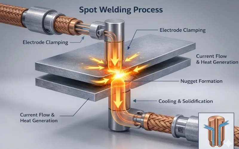
Electrode Clamping
Before any current flows, the electrodes close on the workpiece and apply a controlled, consistent force — typically between 1 and 10 kilonewtons depending on material type and thickness. This phase does more than just hold the sheets together. The clamping pressure:
- Establishes consistent electrical contact between the electrode and the workpiece
- Collapses surface asperities (microscopic surface irregularities) to ensure uniform current distribution
- Expels surface contaminants at the faying interface (the contact surface between the two sheets)
- Pre-positions the metal so that the fused nugget forms at the correct location under pressure
Note: Insufficient electrode force during squeeze causes uneven current distribution and, during the weld phase, localized overheating that results in expulsion — the violent ejection of molten metal from the weld zone. It looks dramatic and produces spatter, but the real problem is the structural void it leaves inside the weld.
Current Flow & Heat Generation
Current flows through the electrode stack for a precisely controlled duration (typically 8 to 400 milliseconds), at amperages ranging from 3,000 to 40,000 amperes, depending on the application. The heat generated follows Joule’s Law: Q = I²Rt, where:
- Q = heat generated (joules)
- I = welding current (amperes)
- R = electrical resistance of the material (ohms)
- t = current flow time (seconds)
Joule’s Law has revealed a critical insight that heat increases with the square of the current. Double the current, and you generate four times the heat. This is why current is the most powerful and most dangerous parameter to adjust. A small change in current causes a disproportionately large change in heat output.
The heat concentrates at the faying surface (the interface between the two metal sheets) because this is where electrical resistance is highest. At this point, the metal heats rapidly, reaches its melting point, and forms the weld nugget, while the surrounding material (and the electrode-workpiece interface) remains in the solid state. This is not an accident of the process; it’s the designed outcome of how resistance distributes through the joint stack.
Nugget Formation
As the temperature rises above the melting point, a small molten zone forms between the sheets, known as the weld nugget. This nugget is the core of the joint and determines its strength. The size and shape of the nugget must be carefully controlled to meet mechanical performance requirements.
- Molten metal forms at the interface under pressure
- Nugget diameter directly affects joint strength
- Uniform nugget growth ensures consistent weld quality
- Excessive heat may cause expulsion or voids
Note: Recent industrial practices incorporate real-time weld monitoring (such as dynamic resistance measurement) to track nugget formation and detect defects during the process, reducing the need for destructive testing.
Cooling & Solidification
After the current stops, the electrodes continue to apply pressure while the molten nugget cools and solidifies. This stage transforms the molten metal into a metallurgical bond. Controlled cooling is essential to avoid internal defects and ensure durability.
- Pressure is maintained to forge the weld during solidification
- Rapid cooling creates a strong but potentially brittle structure
- Controlled cooling improves ductility and fatigue resistance
- Final weld strength is established in this phase
In modern manufacturing, post-weld hold time optimization is used to fine-tune cooling behavior, especially for advanced high-strength steels (AHSS) and lightweight alloys.
Key Parameters in Spot Welding
Controlling spot welding quality is fundamentally about managing key process parameters in balance, not in isolation. Each variable directly affects heat generation, nugget formation, and final joint strength. Below are the most critical parameters explained with practical, up-to-date insights used in modern manufacturing.
Welding Current
Welding current is the primary driver of heat generation (through Joule’s law) in spot welding. Since heat is proportional to the square of the current, even small changes can significantly impact the weld.
- Higher current → faster heat buildup and larger weld nugget
- Lower current → insufficient fusion and weak joints
- Excessive current → expulsion, surface burning, electrode damage
The following table shows the typical current ranges by application:
| Application | Material | Thickness | Typical current range |
| Light auto body repair | Mild steel | 0.8–1.2 mm | 6,000–9,000 A |
| Automotive production (BIW) | HSLA/DP steel | 1.0–2.0 mm | 8,000–14,000 A |
| Stainless steel fabrication | 304 SS | 1.0–1.5 mm | 5,000–8,000 A |
| Aluminum (automotive) | AA5xxx/6xxx | 1.0–2.0 mm | 20,000–35,000 A |
| Micro welding (battery tabs) | Nickel/steel foil | 0.1–0.3 mm | 500–3,000 A |
Welding Time
Weld time is the duration for which current flows through the electrode stack, measured in milliseconds on modern controllers (older systems used electrical cycles, where one cycle = 16.67 ms at 60 Hz or 20 ms at 50 Hz).
Like welding current, weld time directly controls heat input through the Q = I²Rt relationship. But while current affects heat generation quadratically, time affects it linearly (double the time, double the heat). This makes time a more conservative adjustment tool when fine-tuning: a 10% increase in time is predictable; a 10% increase in current is not. Longer weld time allows heat to:
- Spread laterally, increasing nugget diameter
- Penetrate deeper into thicker material stacks
- Compensate for surface contamination or poor electrode condition
However, extended weld time also allows heat to:
- Conduct outward toward the electrode faces, increasing electrode wear
- Heat the outer sheet surfaces excessively, increasing electrode indentation depth
- Create a larger heat-affected zone (HAZ), potentially altering material properties adjacent to the weld
Key note: Advanced welding controllers now use multi-pulse welding schedules (preheat + weld + temper pulses) to improve weld quality, especially for high-strength steels.
Electrode Force
Electrode force ensures proper contact between the sheets and controls electrical resistance at the interface. It serves multiple simultaneous functions throughout the weld cycle:
- Establishes electrical contact resistance: higher force reduces the contact resistance at the electrode-workpiece interface (desirable, to concentrate heating at the faying surface rather than at the electrode contact). Lower-than-specified force means the current generates heat at the electrode face, causing electrode sticking and surface burning rather than internal nugget formation.
- Maintains mechanical alignment: force keeps the sheets in intimate contact at the faying interface, ensuring that the resistance concentration (and therefore heat generation) occurs at the intended location.
- Controls expulsion: during the weld phase, the molten nugget is under pressure from the surrounding solid metal. If the electrode force is insufficient, the expanding nugget can breach the faying surface and expel as spatter. Adequate force acts as a mechanical containment for the nugget during its liquid phase.
Same as welding current, the electrode force has a valid range for each application. Too little force causes poor contact and expulsion. Too much force causes:
- Electrode indentation: the electrode face sinks into the softened surface, leaving a cosmetically and sometimes structurally unacceptable depression
- Shunting increase: excessive force on thin material can deform the sheets, increasing the contact area and reducing current density
- Electrode wear acceleration: higher force increases the rate of electrode face deformation under thermal cycling
Electrode Tip Diameter and Geometry
The electrode face diameter determines current density (current per unit area) at the workpiece contact. Since nugget diameter is a direct function of current density, the relationship between electrode face diameter and nugget size is foundational:
- AWS C1.1 provides the minimum acceptable nugget diameter as a function of material thickness: approximately 4√t (where t is the thickness of the thinner sheet in millimeters). For a 1mm sheet, this means a minimum nugget diameter of 4mm.
- As the electrode faces mushrooms from 5mm to 7mm diameter through wear, the same current now spreads over 96% more area — current density drops proportionally, and nugget diameter decreases below specification.
- This is why a production line that makes acceptable welds at Monday’s startup may be producing cold welds by Friday afternoon with the same programmed parameters.
Electrode face geometry types and selection:
| Face Type | Geometry | Best Application | Key Advantage |
| Flat (F-type) | Flat circular face | Mild steel, standard production | Maximum current density, controlled indentation |
| Dome (D-type/radius) | Spherical radius face | Misaligned assemblies, aluminum | Self-centering, forgiving of angular misalignment |
| Truncated cone (Pointed) | Small flat tip, angled body | High-conductivity materials, tight access | High current density, reaches confined locations |
| Offset/bent shank | Angled electrode body | Restricted access areas | Access to otherwise unreachable weld locations |
Tips: Routine electrode dressing (reshaping) is essential in production lines to maintain consistent weld performance.
Material properties
Material properties play a decisive role in how heat is generated, distributed, and retained during spot welding. Even with identical machine settings, different materials can produce completely different weld results. Key influencing factors include:
- Electrical conductivity: Higher conductivity (e.g., aluminum) reduces heat generation, requiring higher current
- Thermal conductivity: Materials that dissipate heat quickly make it harder to form a stable weld nugget
- Surface coatings: Zinc or oxide layers can create unstable resistance and inconsistent weld quality
- Material thickness & stack-up: Uneven thickness leads to uneven heat distribution
In modern production, engineers rarely rely on fixed parameters. Instead, they use material-specific welding schedules and testing (e.g., peel tests, nugget diameter checks) to fine-tune settings for each material combination.
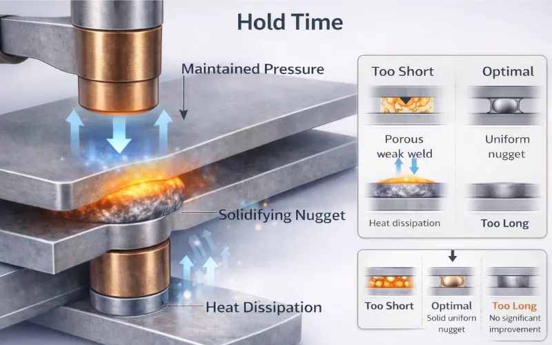
Hold Time
Hold time is the phase where the molten weld nugget solidifies under pressure, directly affecting the final mechanical strength and durability of the joint.
- Maintains pressure to prevent shrinkage voids
- Ensures proper grain structure formation during solidification
- Reduces risk of cracks and internal defects
If the hold time is not properly controlled:
- Too short: weak weld, internal porosity
- Too long: reduced efficiency and unnecessary cycle time
Note: For mild steel, hold times of 100–300 ms are typical. For high-strength steels, particularly martensitic and press-hardened grades, hold times of 300–800 ms or longer may be required to prevent HAZ cracking. For aluminum, shorter hold times are often used because aluminum’s high thermal conductivity means the nugget solidifies rapidly, and extended hold time contributes little additional benefit.
What are The Advantages of Spot Welding?
Spot welding is widely used in manufacturing because it combines speed, efficiency, and consistent quality. Below are the 7 most important advantages that make it a preferred choice in high-volume production:
- High production speed: Each weld takes only milliseconds, enabling fast, large-scale manufacturing with high throughput.
- No filler material required: Eliminates the need for consumables like filler metal or gas, reducing cost and process complexity.
- Excellent for automation: Easily integrated with robotic systems, ensuring consistent quality and reduced labor dependency.
- Energy efficient: Generates heat only at the contact point, minimizing energy waste and reducing thermal impact on surrounding material.
- Strong and reliable joints: Produces durable welds with high shear strength when parameters are properly controlled.
- Minimal surface preparation: Requires less cleaning and preparation compared to other welding methods, saving time and cost.
- Low distortion and clean appearance: Localized heating reduces warping and results in cleaner welds with minimal post-processing needed.
Spot Welding vs Other Joining Methods
Choosing the right joining method depends on factors like material type, thickness, strength requirements, and production volume. Although spot welding stands out in high-speed sheet metal applications, other methods may be more suitable in different scenarios.
| Spot Welding | MIG Welding | TIG Welding | Laser Welding | Riveting | |
| Process type | Resistance (no filler) | Arc + filler | Arc (high precision) | Focused laser beam | Mechanical fastening |
| Speed | Very high | High | Low | Very high | Moderate |
| Material thickness | 0.5–3 mm | 0.8–20+ mm | 0.3–0.5mm | 0.2–3 mm | Unlimited |
| Automation | Excellent | Good | Limited | Excellent | Moderate |
| Joint strength | High (localized) | High | Very high | Very high | Moderate |
| Heat input | Low (localized) | Medium | Low | Very low | None |
| Surface finish | Minor marks | Visible weld bead | Clean finish | Very clean | Visible fasteners |
Keynote:
- Spot welding is ideal for high-volume production of thin sheet metals, especially in automotive and manufacturing industries.
- MIG welding is more versatile for thicker materials and longer weld seams.
- TIG welding provides superior precision but is slower and less suitable for mass production.
- Laser welding offers high precision and minimal distortion but comes with higher equipment costs.
- Riveting is useful when welding is not feasible, but it adds weight and additional components.
Spot Welding Safety Considerations
Spot welding involves high current, pressure, and heat, making safety a critical part of the process. Understanding and controlling potential hazards helps prevent injuries and ensures a safe working environment.
- Electrical hazards: High currents can cause severe electric shock if equipment is not properly insulated or grounded; always check cables and connections before operation.
- Burn risks: Electrodes and workpieces can become extremely hot, so operators should wear heat-resistant gloves and avoid direct contact after welding.
- Mechanical pressure injuries: Moving electrodes applies significant force, creating pinch points that can injure fingers or hands if not handled carefully.
- Fire hazards: Sparks or hot metal can ignite nearby flammable materials, so the workspace should be clean and properly ventilated.
- Fume exposure: Welding coated or contaminated materials may release harmful fumes, requiring adequate ventilation or extraction systems.
- Eye protection: Bright flashes and sparks can damage eyes, so safety goggles or face shields should always be used.
- Equipment maintenance: Worn electrodes, damaged cables, or faulty controls can increase risks, making regular inspection and maintenance essential.
The following proper safety procedures and the use of appropriate protective equipment not only prevent accidents but also help maintain consistent welding quality in industrial environments.
Read more: 8 Most Common Spot Welding Defects and How To Fix Them
Conclusion
Spot welding remains a cornerstone of modern manufacturing thanks to its speed, efficiency, and ability to produce strong, reliable joints. By understanding the process, key parameters, and common challenges, users can significantly improve weld quality and consistency. When properly controlled and applied, spot welding is not just a joining method, but a highly optimized solution for scalable production.
FAQs
Spot welding is primarily used to join sheet metals in industries such as automotive, electronics, and manufacturing, where fast and repeatable joining is required.
A properly made spot weld can be very strong, often comparable to the base metal, depending on the weld nugget size and material properties.
Spot welding does not require a hole, as it joins sheets directly using heat and pressure. If using plug welding instead, the hole size is typically 6–10 mm (1/4″–3/8″), depending on material thickness.
Spot welds are usually removed using a spot weld drill bit or cutter to cut through the weld nugget. Care should be taken to avoid damaging the underlying metal.