Sheet metal bending defects can quietly undermine product quality, driving up scrap rates, rework time, and production costs. Many manufacturers encounter these issues without fully understanding their root causes or long-term impact. This guide outlines the most common sheet metal bending problems and the key factors behind them, helping you recognize warning signs early and improve bending performance with more consistent, reliable results throughout your fabrication process.
Common Sheet Metal Bending Defects
Even with careful planning, sheet metal bending can sometimes result in defects that compromise part quality and structural integrity. Understanding these defects helps fabricators diagnose issues early and implement corrective measures.
Springback
Springback is the elastic recovery of the material after the bending force is removed. It’s influenced by the material’s yield strength and Young’s modulus – higher values generally mean more springback. The bend angle and tooling also play a significant role.
Causes
- Material properties (yield strength, Young’s modulus).
- Bend angle (sharper angles have more springback).
- Tooling (die radius).
How to Fix
- Overbending: Intentionally bending the material slightly past the desired angle to compensate.
- Specialized tooling (such as wiping dies).
- Using software to predict and compensate.
Overbending and Underbending
Overbending results in a smaller bend angle than intended, while underbending results in a larger angle.
Causes
- Worn or damaged dies.
- Incorrect die angles.
- Material variations (thickness, hardness).
- Inaccurate bend allowance calculations.
How to Fix
- Regular tool inspection and maintenance.
- Precise setup and calibration.
- Using the correct bend allowance.
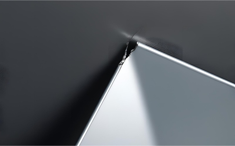
Edge Cracking and Internal Cracking
Cracks can occur on the outside (edge) or inside of the bend, often due to exceeding the material’s ductility. Grain direction relative to the bend line is a significant factor; bending across the grain is generally more prone to cracking than bending with the grain.
Causes
- Low material ductility.
- Too small a bend radius.
- Poor tooling condition.
- Bending across the grain.
How to Fix
- Choosing materials with good formability.
- Using a larger bend radius.
- Annealing (heat treating) the material to improve ductility.
- Ensuring tooling is in good condition.
Wrinkling (Flange Wrinkling and Web Wrinkling)
Wrinkling is the formation of unwanted waves or buckles in the material. Flange wrinkling occurs on the flange (the unbent portion), while web wrinkling occurs in the bend itself.
Causes
- Compressive stresses exceeding the material’s buckling resistance.
- Thin material.
- Inadequate tooling support.
How to Fix
- Using pressure pads or draw beads to control material flow.
- Adjusting bending parameters (such as increasing bend radius).
- Use thicker material (if possible).
Deformation
Deformation, such as bulging or twisting, refers to any unwanted change in shape beyond the intended bend.
Causes
- Uneven pressure distribution.
- Tooling misalignment.
- Material inconsistencies.
- Improper clamping.
How to Fix
- Proper tooling setup and alignment.
- Using consistent material.
- Secure clamping to prevent movement.
- Using shims if necessary to ensure even pressure.
Dimensional Inaccuracies
Dimensional inaccuracies refer to deviations from the intended dimensions of the bent part. This can manifest as incorrect bend angles, lengths, or overall part geometry.
Causes
- Inaccurate Calculations: Errors in calculating bend allowance, bend deduction, or springback compensation.
- Tooling Wear: Worn or damaged tooling can lead to inconsistent bends.
- Machine Calibration: An improperly calibrated bending machine will not produce accurate results.
- Material Variations: Variations in sheet metal thickness or material properties can affect the final dimensions.
- Operator Error: Incorrect setup.
How to Fix
- Precise Calculations: Double-check all calculations and use software tools to verify results.
- Regular Tooling Inspection: Implement a schedule for inspecting and replacing worn tooling.
- Machine Calibration: Ensure the bending machine is properly calibrated according to the manufacturer’s specifications.
- Material Consistency: Use sheet metal from a reputable supplier and verify its properties.
How to Prevent Sheet Metal Bending Defects?
While understanding defects is essential, preventing them is where true manufacturing efficiency begins. Below are proven strategies and expert tips to ensure your sheet metal bending process consistently delivers high-quality results.
Best Practices for Bending Setup
Preventing defects starts with a meticulous setup:
- Tooling Selection: Choose the correct punch and die for the material and desired bend radius.
- Tooling Maintenance: Inspect tooling for wear, damage, and cleanliness before each use.
- Machine Calibration: Ensure the bending machine is properly calibrated and functioning correctly.
- Material Handling: Store and handle sheet metal carefully to prevent scratches, dents, and contamination.
- Material Verification: Confirm the material type, thickness, and properties match the specifications.
- Accurate Calculations: Double-check bend allowance, bend deduction, and springback calculations.
- Checklist: Use a pre-bending checklist to ensure all steps are followed consistently.
Choose the Right Material
Match material properties with bending needs. For tight radius bends, use materials with higher ductility, such as annealed aluminum or low-carbon steel. Notably, when bending along the grain, cracking is more likely. Try to bend perpendicular to the grain direction when possible.
| Bendability | Note | |
| Low-Carbon Steel | Good | Generally easy to bend |
| Aluminum Alloys | Excellent | Very formable, but prone to springback |
| Stainless Steel | Average to good | Requires more force, prone to work hardening |
Account for Springback
Use bend allowance formulas and simulation software to accurately compensate for springback.
Formula:
BA = (π/180) × Bend Angle × (Inner Radius + K-factor × Material Thickness)
Or use bend simulation tools like AutoForm or the SolidWorks Sheet Metal module.
Using Simulation Software for Bending
Finite Element Analysis (FEA) software can be a powerful tool for predicting and preventing bending defects:
- Types of Simulations: Static simulations can analyze stress and strain distribution, while dynamic simulations can model the bending process over time.
- Parameters Analyzed: Software can predict springback, wrinkling, cracking, and other defects.
- Benefits: Optimize tooling design, reduce trial and error, and improve part quality.
- Limitations: Simulation results are only as good as the input data; physical validation is still important.
Quality Control and Inspection
A robust quality control process is essential:
- Visual Inspection: Carefully examine bent parts for cracks, wrinkles, surface defects, and other visible flaws. Look for consistent bend angles and smooth transitions.
- Dimensional Measurement: Use calipers, protractors, height gauges, and CMMs to verify dimensions against specifications.
- Acceptance Criteria: Establish clear acceptance criteria and tolerances for each part.
- Documentation: Maintain detailed inspection records, including measurements, observations, and any corrective actions taken
Conclusion
Bending defects in sheet metal fabrication are common but entirely manageable. By understanding the root causes of issues such as cracking, wrinkling, and springback, and implementing preventive strategies, you can significantly improve part quality and reduce rework costs. Whether you are a hands-on technician or an engineer optimizing workflows, a proactive approach to bending defects leads to increased efficiency, cost savings, and higher customer satisfaction.
FAQs
The most common defect is springback, where the metal slightly returns to its original shape after bending. It often leads to incorrect bend angles and requires compensation during design or setup.
To prevent cracks, ensure you use the correct bend radius for your material, avoid bending along the grain, and use materials with adequate ductility. Also, inspect for micro-cracks or weaknesses in the raw material before bending.
Wrinkling is usually caused by excessive compressive forces during bending or inadequate die support. You can reduce this by adjusting the die width, using stiffer materials, or applying tension during bending.
Simulation tools like AutoForm, SolidWorks Sheet Metal, and BendCAM can predict outcomes and optimize designs. Additionally, CNC press brakes with real-time feedback systems can automatically adjust for angle accuracy and material variability.