Deep drawing is widely used in manufacturing, yet many struggle to understand why defects occur or how to design parts that actually work. Missteps in material choice or process control can lead to costly failures and delays. This guide cuts through the complexity, offering practical insights into the deep drawing process and sheet metal forming essentials so you can make smarter decisions and achieve reliable, high-quality results.
What is Deep Drawing?
Deep drawing is a sheet metal forming process where a flat metal blank undergoes plastic deformation as it is radially drawn into a die cavity by a punch, with control from a blank holder to form a hollow, three-dimensional shape. The process performance depends on key parameters such as draw ratio, forming force, blank holder force, and material properties, which influence thickness distribution and strain distribution, while proper lubrication and optimized tool design (including die radius and punch radius) help prevent defects like wrinkling, tearing, and springback, making it widely used in automotive, aerospace, and packaging industries for efficient mass production.
How Does the Deep Drawing Process Work?
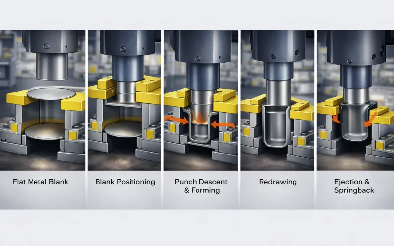
Understanding each stage of the deep drawing process is essential for improving product quality, reducing defects, and optimizing production efficiency. Modern deep drawing is no longer just a mechanical operation. It is a data-driven, highly controlled forming process that combines material science, tooling design, and real-time monitoring.
Blank Preparation
The process starts with preparing a flat metal blank that will be formed into the final shape. The quality of this step directly impacts the entire process.
- The blank must have consistent thickness and smooth, burr-free edges to prevent crack initiation
- Material properties such as yield strength, elongation, and anisotropy (grain direction) influence how the metal flows
- Blanks are often coated with lubricants or protective films to reduce friction and prevent surface damage
- In high-precision applications, laser cutting or fine blanking is used to improve dimensional accuracy
Note: Even small variations in blank quality can lead to defects later, making this step more critical than it appears.
Blank Positioning and Blank Holder Engagement
The blank is positioned concentrically over the die opening. The blank holder, sometimes called a pressure pad, descends and clamps the outer perimeter of the blank against the die face with a controlled force.
This blank holder force (BHF) is one of the most consequential variables in the entire process. Too little BHF and the compressive stress in the flange causes the metal to buckle into wrinkles. Too much BHF and the frictional restraint prevents material from flowing into the die, causing the wall to fracture under tension. The correct BHF creates a narrow operating window, and maintaining it precisely throughout the stroke is what separates good process control from chronic defect production.
Punch Descent and Material Flow
As the punch descends and contacts the blank center, it begins forcing material into the die cavity. This is where the three distinct stress zones of deep drawing emerge simultaneously:
- Base zone (beneath the punch): The metal in contact with the punch face experiences biaxial tensile stress. This zone does the least deforming — it is essentially carried into the die.
- Wall zone: The drawn wall experiences uniaxial tensile stress along its length. This is where thinning occurs, and where fracture initiates if the process is outside its window.
- Flange zone: The remaining blank on the die face experiences radial tensile stress (pulling it inward) combined with circumferential compressive stress (as the blank diameter shrinks, the metal must “compress” tangentially). This compressive stress is what causes wrinkling when uncontrolled.
Redrawing for Deep Parts
When the required depth exceeds what a single draw can achieve (typically when the depth-to-diameter ratio is greater than 0.7–0.8), the part must go through one or more redrawing operations. Each redraw takes the already-drawn cup and draws it again through a smaller die, increasing depth and reducing diameter. Typical reduction ratios per stage:
- First draw: up to 50% reduction in blank diameter
- Subsequent redraws: 20–30% reduction per stage
Work hardening accumulates with each draw. For materials that harden rapidly, such as stainless steel and aluminum, intermediate annealing between redraw stages restores ductility and prevents fracture.
Ejection and Springback
Once the punch reaches full stroke, the formed part is stripped from the punch and ejected. Springback, elastic recovery of the material after forming load is removed, can cause the part to deviate slightly from the die geometry. For most deep-drawn cylindrical parts, springback is modest compared to bent parts, but it must be accounted for in tight-tolerance applications.
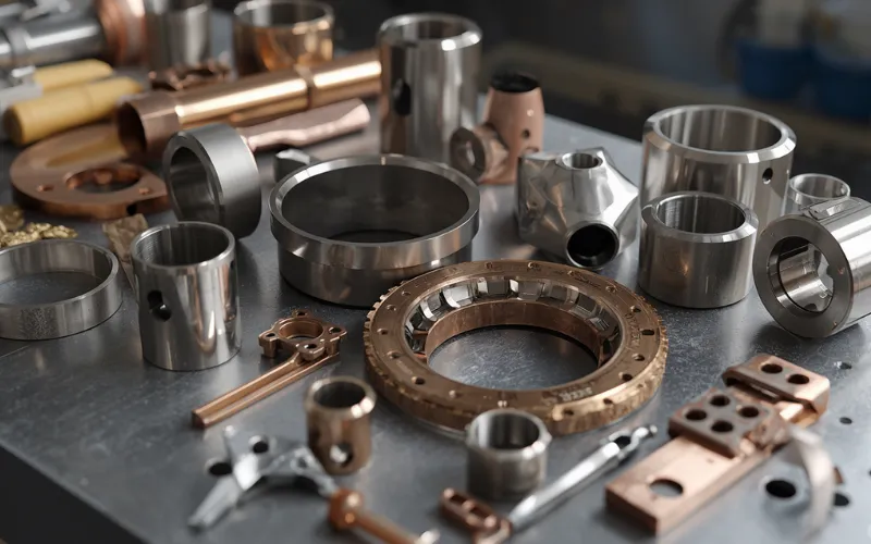
What Materials Are Used in Deep Drawing?
Selecting the right material is a critical first step, as it directly influences formability, product quality, and overall manufacturing efficiency.
Common Deep Drawing Materials
Not every metal can survive the compressive-tensile stress state of deep drawing. The table below maps the most commonly drawn alloys against their formability and practical context, the kind of reference that typically requires cross-referencing three material supplier datasheets to assemble.
| Material | Common grades | Formability | Typical applications | Special considerations |
| Low-carbon steel | DC01–DC06 (EN), AISI 1008/1010 | Excellent | Kitchen sinks, medical trays, and food processing | Most forgiving material; the default choice |
| Stainless steel | 304, 316 (austenitic), 430 (ferritic) | Good to moderate | Austenitic grades work-harden rapidly, require more BHF, and better lubrication | Austenitic grades work-harden rapidly, require more BHF, and better lubrication |
| Aluminum | 1100, 3003, 5052 | Good to moderate | Cookware, beverage cans, aerospace panels | Prone to galling against steel tooling, use chrome or DLC-coated dies |
| Copper & brass | C11000, C26000 | Excellent | Electrical housings, ammunition casings | Excellent drawability but expensive; often justified by conductivity requirements |
| Titanium | Grade 1, grade 2 | Moderate to difficult | Aerospace, medical implants | Often requires warm forming (200–400°C) for deeper draws |
| Inconel | 625, 718 | Difficult | Jet engine components, energy sector | Typically hot, deep drawn, and extreme tool wear |
Material Properties That Determine Drawability
Two material properties matter more than any others, yet they rarely appear on a standard material certificate unless you specifically request them:
- Strain Hardening Exponent (n-value): This measures how uniformly a material distributes plastic deformation. A higher n-value (such as 0.22 for DC04 steel vs. 0.15 for 5052 aluminum) means the material resists localized necking — the precursor to tearing. Always request n-value data from your material supplier for critical deep-drawing applications.
- Plastic Strain Ratio (r-value / Lankford Coefficient): The r-value measures a material’s resistance to thinning relative to its willingness to flow in-plane. An r-value of 1.0 means equal resistance; values above 1.0 (such as 1.6–2.2) for deep-drawing-grade steel indicate the material prefers to flow radially rather than thinly, which is exactly what deep drawing demands. The normal anisotropy (r̄) predicts overall drawability; the planar anisotropy (Δr) predicts earing severity.
- Elongation: A minimum total elongation of 20–30% is generally required. Below this, the material lacks the plastic deformation capacity to survive the draw.
- Grain Size: Finer grains (ASTM 6–8) produce smoother surfaces and more uniform forming. Coarse grains cause an “orange peel” texture on the drawn part — an aesthetic and sometimes functional defect.
Deep Drawing Defects and How to Prevent Them
This defect-cause-remedy matrix consolidates troubleshooting knowledge that typically takes years on the production floor to accumulate.
| Defects | What it looks like | Root cause | How to fix |
| Wrinkling | Folds/waves in flange or wall | BHF too low; die radius too large | Increase BHF; reduce die radius; add draw beads |
| Tearing/ Fracture | Split at punch radius or wall | BHF too high; LDR exceeded; poor lubrication | Reduce BHF; verify LDR; improve lubrication; anneal |
| Earing | Uneven cup height (ears at 0°/90° or 45°) | Planar anisotropy (Δr ≠ 0) | Use material with low Δr; compensate with a non-circular blank shape |
| Springback | Part geometry deviates after ejection | Elastic recovery after forming | Over-bend compensation; ironing; stress relief anneal |
| Galling / scoring | Scratches or material transfer on part/tool | Inadequate lubrication; soft die surface | Apply proper lubricant; polish and coat tooling (TiCN, DLC) |
| Excessive thinning | Wall measurably thinner than blank | Clearance too tight; BHF too high | Adjust punch-die clearance; reduce BHF |
| Orange peel | Rough, textured surface on part | Split at the punch radius or wall | Split at the punch radius or wall |
Wrinkling: The Compressive Buckling Problem
Wrinkling occurs when circumferential compressive stress in the flange exceeds the material’s resistance to in-plane buckling. Think of it as trying to push a flat sheet into a smaller circle; the excess material has nowhere to go but upward into folds. The systematic fix follows this priority sequence:
- Increase blank holder force first — it is the most direct control variable
- Add draw beads to the blank holder face to create controlled restraint around the perimeter
- Reduce the die radius if wrinkling occurs under the die face
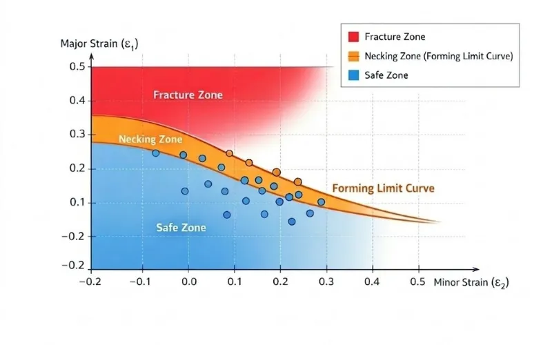
Fracture: When Tension Wins
Fracture at the punch radius is the most serious defect; it produces scrap with no recovery path in that forming stage. It occurs when the tensile stress in the wall exceeds the material’s local tensile strength, which happens when:
- The LDR is exceeded (too much material trying to flow through too narrow a punch)
- BHF is too high (preventing material flow, forcing the wall to stretch instead of drawing more material in)
- Lubrication is insufficient (friction consumes the force that should be driving material flow)
The Forming Limit Diagram (FLD) is the engineering tool used to predict fracture before it happens. It maps combinations of major and minor strains that a material can sustain before necking or fracture. Simulation software like AutoForm computes FLD proximity throughout the part and flags at-risk regions before any physical tooling is cut.
Earing: The Anisotropy Signature
Earing, the formation of wavy peaks and valleys around the rim of a drawn cup, is a direct fingerprint of the material’s crystallographic texture. Sheet metal rolled in one direction develops preferential grain orientations that make the material stronger (and less drawable) in certain directions. The severity of earing is quantified as:
Earing % = (h_max − h_min) / h_avg × 100
For most functional applications, earing below 3% is acceptable. Above that, the non-uniform rim height causes trimming inconsistency and can interfere with secondary operations. The solution lies in material specification, where low-earing grades are produced with controlled rolling and annealing practices that minimize planar anisotropy (Δr ≈ 0).
What are The Advantages of Deep Drawing?
Understanding the key advantages of deep drawing helps explain why it remains a preferred method for producing high-quality, complex metal components at scale.
- Seamless construction: no welds, joints, or fasteners. Critical for pressure vessels, food-contact surfaces, and medical enclosures where hygiene and structural integrity matter.
- High production speed: transfer press lines produce hundreds of parts per minute at per-unit costs below $0.10 for simple geometries.
- Work hardening strengthens the part: the drawn wall can be 15–30% stronger than the original sheet, reducing the need for thicker (heavier, costlier) starting material.
- Excellent material utilization: scrap rates of 10–20% are typical, far below the 60–80% common in CNC machining of similar geometries.
- Outstanding repeatability: once optimized, deep drawing processes routinely achieve Cpk > 1.33 across millions of cycles.
- Superior surface finish: parts often come out with smooth, uniform surfaces, reducing or even eliminating the need for additional finishing processes like machining or polishing.
- Capability for complex geometries: deep drawing can produce intricate shapes with tight tolerances that would be difficult or costly to achieve using other forming methods.
- Reduced assembly requirements: by forming parts in a single piece, deep drawing minimizes the need for secondary joining operations, lowering labor costs and improving overall product reliability.
Key Parameters in Deep Drawing
The difference between a successful draw and a scrapped part comes down to six variables. The following table consolidates the critical ranges that production engineers work within daily, data typically scattered across multiple textbooks and tribal knowledge.
| Parameter | Definition | Typical range | Consequence |
| Drawing Ratio (DR) | Blank diameter ÷ Punch diameter | 1.6–2.2 (single draw) | Exceeding the limiting drawing ratio (LDR) causes wall tearing |
| Blank Holder Force (BHF) | Clamping force on the flange | 0.5–3% of UTS × blank area | Too low → wrinkling, too high → tearing |
| Punch Speed | Velocity of the punch through the stroke | 5–300 mm/s (hydraulic), up to 1,000 mm/s (mechanical) | Too fast → strain-rate-induced cracking in sensitive alloys |
| Die Clearance | Gap between punch OD and die ID | 110–130% of sheet thickness (drawing), 100–105% (ironing) | Too tight → excessive thinning, too loose → wrinkling in the wall |
| Die Entry Radius | Radius at the top edge of the die opening | 4–10× sheet thickness | Too sharp → tearing at die lip, too generous → loss of flange control |
| Lubrication | Friction management between blank, die, and punch | Petroleum oils, dry films, phosphate-soap coatings | Inadequate lubrication → galling, scoring, and premature tool wear |
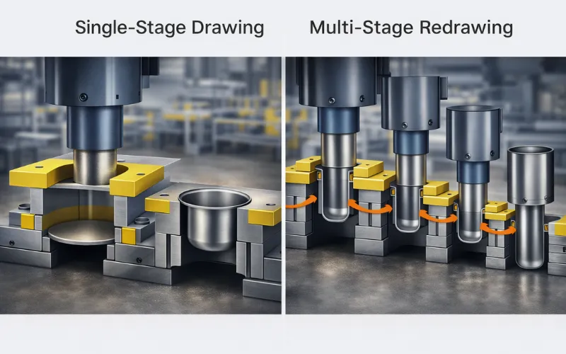
Single-Stage vs Multi-Stage Redrawing
When a part’s depth-to-diameter ratio exceeds the LDR for a single draw, the part must be formed progressively across multiple stages. Each successive redraw reduces the diameter and increases the depth, but with diminishing returns, because the metal work-hardens with each stage.
| Stage | Typical diameter reduction | Cumulative depth increase | Intermediate annealing needed? |
| First draw | 40–48% | Moderate | No |
| Second draw | 25–30% | Significant | Usually no |
| Third draw | 16–20% | High | Often yes |
| Fourth draw + | 12–15% | Very high | Almost always |
Design Guidelines for Deep Drawing (DFM Checklist)
The following rules, applied during part design, will reduce tooling cost, shorten development time, and minimize defect risk:
- Depth-to-diameter ratio: Target ≤ 2.0 per draw stage. Exceeding this requires multi-stage tooling, which roughly triples the cost per added stage.
- Bottom inside radius: Minimum 1× sheet thickness; recommended 3–4× for reliable forming.
- Wall corner radius (box draws): Minimum 3× sheet thickness. Every millimeter of additional corner radius measurably reduces peak forming stress.
- Wall draft angle: Apply 1–3° taper to ease ejection and reduce die wear.
- Flange width (if retained): Minimum 3× sheet thickness for structural integrity.
- Symmetry: Design symmetrically wherever possible. Asymmetric parts require asymmetric blank shapes, draw beads, and segmented blank holders — all of which add cost.
- Secondary features: Holes, slots, and embossments in the cup wall should be added after drawing as secondary pierce or form operations, never during the draw stroke, where they act as stress concentrators.
Achievable Tolerances
Below are the achievable tolerances in the manufacturing process, along with typical ranges and key notes:
| Dimension | Typical tolerances | Notes |
| Diameter | ±0.05 to ±0.25 mm | Tighter with ironing |
| Depth | ±0.1 to ±0.5 mm | Hardest dimension to control |
| Wall thickness | Expect 10–25% thinning at the punch nose | Dependent on the tool surface and lubrication |
| Surface finish | Ra 0.4–1.6 μm | Expect 10–25% thinning at the punch nose |
How To Choose The Right Deep Drawing Metal Parts Manufacturer?
Choosing the right deep drawing manufacturer is essential to ensure product quality, cost efficiency, and long-term production stability. A capable partner does more than just produce parts. They help optimize design, reduce defects, and improve overall manufacturability. When evaluating a manufacturer, consider the following key factors:
- Technical expertise & experience: Look for proven experience in deep drawing and the ability to handle complex geometries, tight tolerances, and support design-for-manufacturability (DFM).
- Manufacturing capabilities: Ensure they have suitable press capacity, tooling systems, and can support both prototyping and high-volume production.
- Quality control standards: Check for certifications (e.g., ISO 9001) and strong inspection processes to consistently prevent defects like wrinkling or tearing.
- Material knowledge: A reliable manufacturer should understand different materials and recommend the most suitable option for your application.
- Tooling & engineering support: In-house die design and the ability to optimize tooling can significantly reduce cost and production issues.
- Cost efficiency: Transparent pricing and the ability to optimize cost at scale are more valuable than simply offering the lowest quote.
- Communication & reliability: Clear communication, on-time delivery, and proactive problem-solving are critical for smooth collaboration.
Ultimately, the right manufacturer is one that not only meets your specifications but also contributes to better design decisions and consistent production performance over time.
Conclusion
Deep drawing remains a highly efficient and reliable process for producing strong, seamless metal components at scale. By understanding how the process works, controlling key parameters, and applying proper design guidelines, manufacturers can significantly reduce defects and optimize performance. Choosing the right material and manufacturing partner further ensures consistent quality and cost efficiency. Ultimately, success in deep drawing comes from aligning design, process, and expertise to achieve the best possible results.
FAQs
Blank size is calculated based on volume constancy; for simple cups: D₀ ≈ √(D² + 4Dh), with adjustments for thinning and trimming in practice.
Deep drawing forms hollow parts from sheet metal using a punch and die, while bar drawing reduces the diameter of solid rods or wires by pulling them through a die.
Defects are strongly influenced by material properties. Low ductility leads to tearing, high anisotropy causes earing, and poor formability increases wrinkling and uneven thickness, making material selection critical for defect control.