Laser welding defects can quickly undermine weld strength, appearance, and productivity, especially when small process errors go unnoticed. If you’re struggling with porosity, cracking, spatter, or inconsistent penetration, understanding their real causes is the key to fixing them fast. This guide breaks down the most common laser welding defects and practical solutions you can apply immediately to improve quality and prevent rework. Keep reading to optimize your welding process with confidence.
What Are Common Laser Welding Defects?
Laser welding can create strong, precise joints; however, even slight variations in material condition, shielding gas, or machine parameters can lead to defects that weaken the weld. Understanding the most common laser welding defects and what causes them is the first step toward diagnosing issues and improving weld quality.
Porosity and Gas Pores
Porosity appears as small, spherical voids in the weld, visible as dark spots or gray shadows during inspections. Surface porosity is visible, but subsurface porosity is more dangerous because it can’t be seen.
Causes
- Contaminated shielding gas from low purity or moisture in old bottles can affect weld quality.
- Gas flow below 15 CFM cannot maintain a protective atmosphere, while typical flows range from 20-40 CFM, depending on nozzle design.
- Contaminated material surfaces release gases during heating, causing weld defects.
- Molten weld metal cools too fast for dissolved gases to escape before solidification.
- Moisture in gas lines introduces water vapor into the weld, leading to defects
Solutions
- Replace the shielding gas bottle and verify that its purity is at least 99.99%.
- Increase gas flow by 5-10 CFM increments and test the weld for improvement.
- Clean the component surface thoroughly with a wire brush or solvent before welding to prevent oxidation and trapped gases.
- Install a gas line dryer if porosity continues despite other corrections.
- Reduce travel speed by 10% to extend dwell time and allow trapped gases to escape before solidification.
Cracks (Solidification and Thermal)
Cracks are breaks in weld metal, forming at the centerline or heat-affected zone. They are critical because they can grow under stress and cause failure.
Causes
- Rapid heating followed by rapid cooling creates tensile stress that exceeds material strength, especially when cooling faster than 100°C per second
- Steels with more than 0.4% carbon are particularly crack-susceptible, so cooling must be controlled below the material-specific threshold
- Certain alloys, such as 4140 steel, some stainless grades, and aluminum-copper alloys, have inherent cracking tendencies
- Constrained geometry traps residual stress that exceeds material yield strength after cooling
- Unpreheated material undergoes rapid expansion and contraction cycles that create micro-cracking
- Overly rigid clamping prevents normal thermal expansion and concentrates stress
How to Fix
- Preheat material to 150-400°C, depending on composition, with steels over 0.35% carbon typically requiring at least 250°C
- Reduce laser power by 5-10% and increase travel speed slightly to control thermal gradients and reduce cooling rate
- Use symmetric weld patterns on multi-weld assemblies by welding both sides alternately to balance stress distribution
- Apply post-weld stress relief for critical applications, typically 850°C for 30 minutes for steel, followed by controlled cooling
- Verify material composition before welding using chemical analysis certificates, and refuse material outside specification
- Loosen fixturing slightly after preheating to allow controlled thermal expansion
Spatter and Splash
Spatter is molten metal from the weld that sticks to surfaces. Excessive spatter signals instability, and fine particles are harder to clean.
Causes
- Excess laser power relative to material thickness creates violent molten pool agitation, and reducing power by 10-15% decreases spatter by 30-50%
- Slow travel speed increases dwell time, destabilizes the molten pool, and increases spatter ejection
- Beam focus offset by as little as ±0.5 mm from the material surface significantly increases spatter generation
- Contaminated material surfaces with oxides or oils reduce surface tension stability, allowing easier spatter ejection
- Poor nozzle design or incorrect angle creates shielding gas turbulence that ejects molten particles
Solutions
- Reduce laser power by 5-15% while maintaining penetration, verified with a cross-section test
- Increase travel speed slightly by 2-5% to reduce dwell time
- Verify the beam focus position is exactly at the material surface using a focus indicator or zero-gap test
- Clean the nozzle and ensure the gas flow pattern is smooth without turbulence
- Apply anti-spatter coating to the surrounding material to reduce cleanup time and protect precision surfaces
- Optimize nozzle angle to 30-45 degrees from vertical to improve gas coverage
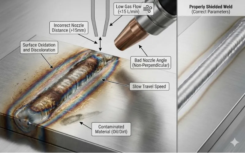
Surface Oxidation and Discoloration
Surface oxidation, seen as discoloration, signals poor shielding and possible deeper weld oxidation.
Causes
- Nozzle positioned too far from the weld allows atmospheric oxygen to enter and create shielding gaps
- Gas flow below 20 CFM fails to maintain a protective atmosphere, with 25-35 CFM recommended for most applications
- Non-optimal nozzle angle creates turbulent gas flow with gaps in coverage
- Slow weld travel speed increases exposure time, allowing oxidation to form
- Contaminated or rusty material surfaces reduce shielding effectiveness
Solutions
- Reposition the nozzle to 10–12 mm from the surface to maximize shielding gas coverage
- Increase gas flow by 5–10 CFM if oxidation persists
- Increase travel speed by 5–10% to reduce oxidation exposure time
- Improve pre-weld surface cleaning to remove contaminants
- Optimize nozzle angle to 30–45 degrees for better gas distribution
- Apply a backup shield using flexible shielding tape or backup gas if side oxidation occurs
Spalling and Chipping
Spalling is the ejection of small chips from the weld surface, indicating brittle weld metal that fractures under solidification stress. It occurs more in some high-strength alloys
Causes
- Certain alloys have inherent brittleness, with precipitation-hardened stainless steels being particularly prone
- Unstable laser power creates non-uniform cooling and stress concentration
- Poor beam quality with M² greater than 1.5 creates erratic heating patterns
- Rough or contaminated surfaces concentrate stress
- Extremely fast cooling in thin materials can cause spalling
How to Fix
- Verify laser power stability using a power meter every month
- Reduce power fluctuations through laser system maintenance or parameter adjustment
- Optimize beam quality through system alignment or service
- Improve pre-weld surface preparation to eliminate stress concentration points
- Reduce the cooling rate using backing plates or heat sinks
Inclusions (Refractory and Metallic)
Inclusions are trapped foreign materials that weaken welds, detectable only by radiography, ultrasound, or metallography.
Causes
- Dirty or worn nozzles and contaminated filler material introduce impurities into the weld
- Poor surface cleaning allows oxides and foreign material to get trapped during welding
- Impure shielding gas can deposit particles into the weld
- Low-quality filler material contains inclusions
- Rust or other contaminants on the base material reduce weld quality
Solutions
- Implement a strict nozzle inspection and replacement program, replacing every 20-30 operating hours
- Establish a pre-weld surface cleaning procedure using wire brushing, solvent, or grinding
- Verify shielding gas purity with documentation
- Source filler material from certified suppliers with quality certification
- Inspect base material for visible contamination before welding
- Perform ultrasonic testing on critical welds to detect inclusions
Keyhole Instability and Collapse
Laser keyhole welding can become unstable, causing inconsistent penetration, porosity, and irregular bead profiles.
Causes
- Intermittent speed changes destabilize cavity pressure balance
- Unstable laser output or poor beam quality creates erratic heating
- Batch-to-batch material differences affect molten metal surface tension
- Insufficient backup gas pressure fails to support the keyhole cavity
- Off-axis nozzle positioning creates an asymmetric gas pressure distribution
Solutions
- Maintain consistent travel speed using a servo-controlled motion system
- Verify laser output stability with power meter checks
- Optimize beam characteristics through system alignment or service
- Increase backup gas pressure to 15-20 bar to stabilize the keyhole cavity
- Verify nozzle alignment to center on the weld path
- Monitor beam position feedback if the system is equipped with sensors
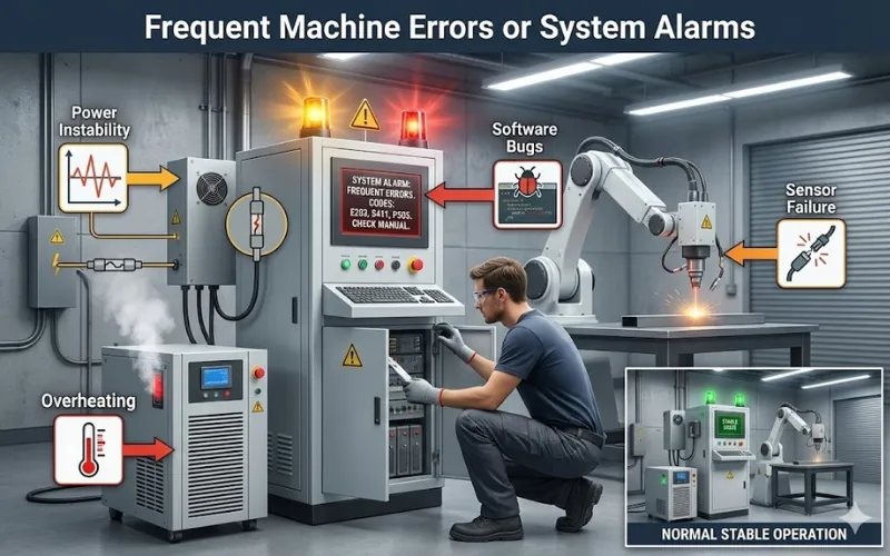
Frequent Machine Errors or System Alarms
Unexpected shutdowns and alarms interrupt production.
Causes
- Power instability
- Software bugs
- Overheating or sensor failures
Solutions
- Stabilize the power supply using a UPS
- Update software regularly
- Clean sensor areas
- Check coolant flow and temperature
A simple loose cable can trigger downtime costing thousands per hour.
How to Prevent Laser Welding Defects?
Prevention in laser welding is not just about reacting to defects after they occur; it is about building a stable, controlled, and repeatable process from the very beginning. By managing material quality, machine parameters, environment, and process consistency, most laser welding problems can be avoided before a single defect appears.
Maintain Strict Material Cleaning and Preparation
Most laser welding defects originate from contamination on the material surface. Oil, grease, rust, paint, or moisture will vaporize during welding, creating porosity, inclusions, and unstable weld pools.
- Clean surfaces with solvent (acetone or isopropyl alcohol)
- Remove oxide layers by light grinding or wire brushing
- Completely dry parts before welding
- Store materials in low-humidity conditions
This single step significantly reduces porosity, spatter, and surface oxidation.
Optimize Shielding Gas Type, Purity, and Flow Rate
Shielding gas protects the molten weld pool from atmospheric oxygen and nitrogen, which cause oxidation and pores.
- Use high-purity gas (≥ 99.99%)
- Maintain flow between 20-40 CFM, depending on material and nozzle
- Use argon or helium for most metals
- Install moisture traps or gas dryers in the line
Correct shielding prevents discoloration, porosity, and keyhole instability.
Match Laser Power and Travel Speed Correctly
Incorrect energy input is the main cause of cracking, lack of fusion, excessive spatter, and burn-through.
- Increase power for thicker materials, reduce it for thin sheets
- Slightly increase the speed if overheating occurs
- Slightly reduce speed if penetration is insufficient
- Keep power fluctuation within ±5%
Stable energy control produces consistent penetration and strong welds.
Set Accurate Focus and Nozzle Position
Even a small focus error (±0.5 mm) can create an unstable melt pool and irregular weld bead.
- Set focus at or slightly below the material surface
- Keep nozzle distance at 10-12 mm
- Align the nozzle perfectly with the weld path
- Recalibrate focus when changing material thickness
This prevents spatter, lack of fusion, and irregular bead shape.
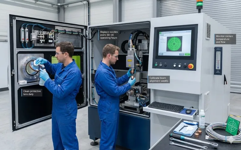
Implement Regular Machine Maintenance and Calibration
Dirty optics, worn nozzles, and unstable power delivery are silent causes of recurring defects.
- Clean protective lens daily
- Replace nozzles every 20-30 operating hours
- Calibrate beam alignment weekly
- Monitor coolant temperature and flow
Regular maintenance alone can eliminate over 50% of recurring laser welding defects in production environments.
Conclusion
Understanding common CO2 laser cutting problems and knowing how to address them is essential for keeping your machine running at peak performance. By quickly diagnosing issues, applying effective fixes, and following a consistent preventive maintenance routine, you can minimize downtime, extend equipment life, and maintain high-quality cutting results for every project.
FAQs
A noticeable drop in cutting ability, especially on materials you previously cut with ease, is a key indicator. You can confirm by measuring output with a laser power meter. If the reading is significantly below the rated power (typically <80%), it may be time for replacement.
A cracked lens should always be replaced. Cracks distort the beam, reduce cutting performance, and can cause dangerous heat buildup, leading to further equipment damage.
The two biggest culprits are an uneven machine bed and mirror misalignment. Both can alter the beam’s focus point, causing one side of the work area to cut better than the other. Regular leveling and alignment checks solve this.
Absolutely yes. Updates often include bug fixes, improved compatibility with file formats, and better motion control algorithms. Keeping your firmware and software in sync helps avoid glitches and unexpected errors.